A weblog focused on interesting circuits, ideas, schematics and other information about microelectronics and microcontrollers.
E-books
Disclaimer
Because I have not tested all electronic circuits mentioned on this pages, I cannot attest to their accuracy; therefore, I do not provide a warranty of any kind and cannot be held responsible in any manner.
My first experiments with accelerometers
29. April 2008 - 16:59 — admin
...or Would you like to built your own Wiimote? :)
I've obtained a couple of MMA7340 accelerometers from Freescale a week ago. MMA7340 is a 3-axis accelerometer with analog output, powered by 3.3V, so it fits perfectly to my Stellaris ARM eval board.
Yesterday I've made an "universal breadboard module" with this accelerometer. One thing must be said before: LGA package is very ugly to solder by hand. But it's not impossible. Lets look at the PIN connections:
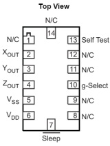
These pads are 0.5x0.8mm small, so it is a little bit tricky to work it around. Here is my process:
1. Take the universal PCB with 0.1" pitch.
2. Cut off suitable piece of PCB, at least 4x4 pins
3. Put a glue drop to the center of the PCB and place the MMA7340 upper side down. Let it stick.
4. Solder the pinhead to the left and right, as shown below.
5. Take a very thin wire (I've used a copper cable, untwisted to elementary thin wires) and solder as shown. Use the soldering paste. A lot of soldering paste!
... and voila! You've the simple accelerometer's module you can use in the breadboard.
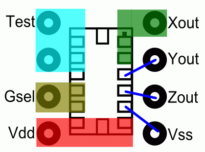
You can solder over the non-connected pins (the different color areas) and you can sold tight the /SLEEP pin (at the bottom edge) with the neighbour Vdd pin (3.3V). You can also sold together Test area and GSel area and connect it to the Vss (ground). This way the hardest thing to soldering is that three blue wires. They must be done perfectly. So - good luck and sure hand! ;)
You can make a bigger module with decoupling capacitors connected between Vdd and Vss and between analog outs and ground, as described in the datasheet.